Signal cycle and split optimization each refer to signal programs of individual signal controllers. Offset optimization, however, is used to optimize the offset between the signal times of neighboring nodes in such a way, that vehicles can pass several consecutive signal controls on green. The general aim is to minimize the total wait time for all vehicles at signalized nodes (main nodes).
|
Notes: Attributes of the node geometry have no effect on coordination. In particular, the stop line position per lane is not taken into consideration. Signalized nodes (main nodes) without a valid signal program are considered to be switched off and are not considered in signal coordination. |
Signal coordination as a component of network-wide signal optimization is suitable for the optimization of signal systems in a network, not only along a linear corridor, as it corresponds with the traditional optimization of the progressive signal system.
Good coordination requires that the signal controllers either have the same cycle times or that the cycle times at least have a simple ratio (for example 2:1). Furthermore, signal controllers have to be located close to each other, otherwise the platoon will have broken up so heavily by the time it has reached the next signal controller, that the arrivals will virtually be uniformly distributed and the wait time cannot be influenced through the choice of the offset. It is therefore generally not sensible to coordinate all signal controllers in one network. You determine which signal controllers should be coordinated by defining signal coordination groups and assigning them signal controllers (User Manual: Managing signal coordination groups). By default, signal controllers are not assigned to any signal coordination group and are not coordinated.
For each signal coordination group define the set of the cycle times which are permitted for the corresponding signal controllers. Please make sure that the cycle times actually make coordination possible. Two signal controllers with cycle times of 60 s and 65 s can generally not be coordinated because the platoon in each cycle takes place at a different cycle second. Suitable cycle times therefore have a small LCM (least common multiple), for example, the family { 60 s, 80 s, 120 s } with LCM = 240 s. Signal coordination optimizes offset times for each signal coordination group separately and takes those signal controllers into consideration with cycle times belonging to the permitted cycle times of the group. Signal controllers with a deviating cycle time are ignored. Corresponding notes are logged in the message window.
Important for coordination is the behavior of the vehicle platoon during the journey from one signal controller to another. Visum determines platoons based on assignment paths for one or more selected PrT demand segments. From all these saved paths, Visum determines how many vehicles on their way first pass signal group SG1 of the signal controller SC1 and then signal group SG2 of the signal controller SC2. We call such a combination of two consecutive signal groups with one volume a coordination path leg or shorter path leg.
A path leg is relevant for the coordination if the following properties apply.
- The path leg starts and ends at signal controller of the same coordination group.
- The path leg contains no nodes (main nodes) of controller type All-way stop.
- The path leg passes through the node (main node) of controller type two-way stop only in the direction of the major flow.
- The path leg does not pass through other signalized nodes (main nodes).
- The travel time on the path leg is short enough so that a significant platoon is retained (specification below).
- No link along the path leg exceeds a threshold for the saturation.
All conditions except for the first one are aimed at a platoon to be retained along the path leg.
For the path legs, the vehicles are determined from the assignment paths, as described above. To give a sequence of path legs a higher influence during optimization, you can create user-defined paths and define a weight for them. If a path leg is then determined to be on a user-defined path, the volume is weighted accordingly during optimization.
The procedure is based on the assignment paths and optimizes the signalization for these paths. So the assignment paths are treated roughly like desire paths. Therefore, it is important that they also correspond to such ideal paths as far as possible. Special care must thus be taken to ensure that the assignment paths are not influenced by existing (non-optimal) signalization.
This is best achieved through robust static assignment, where desirable paths (e.g., along a signal controller coordination group) are particularly attractive. Signal controllers and other wait times at intersections can be modeled by the usual fixed turn penalties. The subordinate network should be made sufficiently unattractive by slow base speeds (v0, speed in the unloaded network). The goal of the static assignment is not to map the actual state as accurately as possible, but to generate the desired and also realistic assignment paths for which the signalization is to be optimized.
Optimization treats the traffic flows on all path legs independently. In each case it is assumed that within a cycle, all vehicles start as a platoon at the beginning of the green time. This means that beginning with the green time start, outgoing vehicles flow off with the saturation flow rate qmax, until the volume per cycle has been exhausted. The following applies:
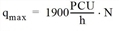
Here, N is the effective number of lanes for the turn. If the green time duration is insufficient and does not allow the volume allocated to a cycle from the assignment to exit with qmax, Visum ignores the excess volume.
The breakup of the platoon caused solely by different vehicle speeds is described by Robertson's platoon development formula. This model discretely divides the time in increments (in Visum of 1 s) and displays the number at time t‘, at which a vehicle arrives at the end of a path leg as a function of the number at time t < t‘, at the beginning of the path leg departing vehicle.
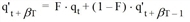
where
|
q‘t |
the number of vehicles arriving at the end of the path leg in time step t |
|
qt |
the number of vehicles departing at the beginning of the path leg in time step t |
|
F |
|
|
T |
travel time tCur on the path leg |
 with specified constants
 For the calculation of queue lengths, we assume idealistically that separate lanes of sufficient length exist for separate signal groups at an approach. Visum generally assumes "vertical" queues for signal coordination and does therefore not consider spillback upstream over several links or have an effect on the capacity of the turns of other signal groups.
For the evaluation of the progression quality, Visum calculates a number of skims which are used throughout literature. In the subsequent formulas CT determines the cycle time, GT the green time and qt the number of vehicles arriving at a node in time step t.
Platoon index =  with
with 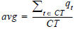
This size measures the "distance" of a volume profile of an equal distribution. The value varies from 0 (equal distribution) to 2 (for a distinct platoon). A high value means that coordination is worthwhile at this node, because the arriving vehicles are focused on part of the cycle time, so that there is a chance of moving the green time there, by changing the offset time.
Vehicles at green =  .
.
This size directly measures how well coordination works. It calculates which part of the volume passes the node without stopping at the signal controller.
Platoon ratio = 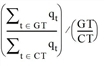
The size also measures how well coordination works, whereas high values imply good coordination. Especially high values are achieved when a large share of arrivals enter at green, although the green ratio itself is smaller.
The platoon ratio PR is the basis for the important ArrivalType parameter in waiting time calculations according to HCM.
ArrivalType = 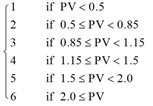
Queue length queuet at a signal group to cycle second t results from the difference of cumulative inflows and exit flows. For this calculation, Visum also calculates the delays of travel times with specified arrival time in the queues and hence, the mean and total wait time.
Input attributes with effect at signal coordination
Signal coordination accesses the network objects and the input attributes displayed in Table 121.
|
Note: Node geometry attributes such as the stop line position, for example, are not regarded for signal coordination. |
|
Network object |
Attributes |
Note |
|
PrT paths of the selected demand segments |
Volumes from assignment paths |
From assignment For dynamic assignment paths (SBA, PDV), volumes can be restricted to a time range. If the time range is not restricted and volumes (AP) are used, a factor for conversion to hourly volumes must be specified. |
|
PrT path set with user-defined PrT paths |
Weighting attribute |
Value of the weighting attribute (UDA) at the user-defined path of the selected path set |
|
Transport system |
Passenger car units (PCU) |
Conversion of volumes into passenger car units This value is used to determine if a path leg exceeds the volume capacity ratio. |
|
Links |
Capacity PrT |
The capacity is used to determine if a path leg exceeds the volume capacity ratio. Static assignment result: volume capacity ratio as volume in PCU/capacity Dynamic assignment result: volume in PCU/ capacity Both values are entered as hourly values. |
|
Links, turns, main turns |
Freely selectable attribute |
Is interpreted as travel time and will be summed up for travel time calculation per path leg. |
|
Signal controller with all components |
All |
Signal times and cycle time of the currently set signal program, mapping of signal groups and lane turns, selection of a reference signal controller that has an offset = 0. |
|
Signal coordination groups |
Cycle time family and assigned signal controller |
Grouping of the signal controllers to be coordinated collectively |
Table 121: Input attributes with an effect on signal coordination
Output attributes at signal coordination
The effect of the signal coordination is primarily to assign the optimal value to the offset attribute of the current signal programs of the coordinated signal controller.
Alongside that, all skims listed above can be calculated for measuring the progression quality. Their definitions first of all refer to a single path leg. In order to easier display results in a network model, Visum aggregates the values of all skims on links and saves the results as link attributes. Visum allocates the attributes at all approach links to signalized nodes which have a volume of > 0. All link attributes for signal coordination results are contained in Table 122.
|
Note: By the name component 'SC coord', the attribute SC coord arrival type is indicated as signal coordination output attribute. It is not identical to the ICA arrival type attribute, which is used as entry for ICA calculation. If you want to calculate the ICA impedance with an arrival type which corresponds with the given offset time intervals, first perform the Signal offset analysis and then copy the SC coord arrival type values to the ICA arrival type attribute. |
